Installation#
The site can be prepared before the delivery of Digiscan, as per XD4100 Installation drawing.
Unpacking#
The Digiscan is packed in a convenient reusable hard Fiber Foam Lined shipping case. The Junction Box and Standardization Fixture are shipped in separate packing.
Mounting#
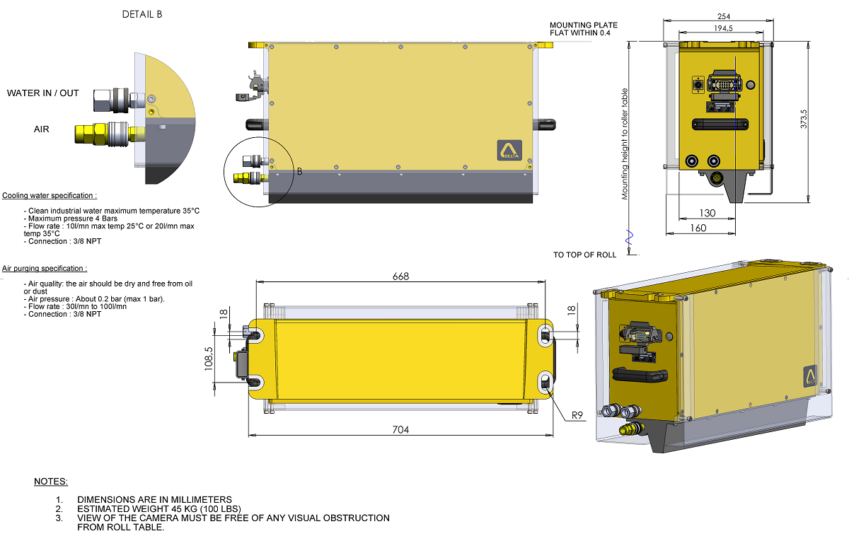
The gauge will be mounted horizontally and centered over the roll table. The mounting heigh depends on the site data. The gauge support should be sufficiently rigid and access to the gauge should be provided for maintenance and inspection. For details on the mounting support refer to the chapter “XD4100 Dimensions”
Note: DigiScan XD4100 is to be mounted only when site is fully ready.
Water connection#
Cooling Water connection is to be made at the water In and Water Out.
- Cooling water specification:
Clean industrial water maximum temperature 35°C
Maximum pressure 4 bars
Flow rate: 10 l/min max temp 25°C or 20 l/min max temp 35°C
- Cooling circuit:
Material: Stainless steel coil
Connection: quick disconnect (3/8 NPT)
Note: The gauge may be subject to high ambient temperature and high infrared radiation from the hot strip. Water cooling should be kept in operation even if the gauge is not electrically connected. The maximum temperature of the gauge not operating is 70°C and operating 50°C (without water cooling).
Note: In case of temperature alarm, check the water flow. If the water flow cannot be immediately restored, power down the gauge and remove the gauge from the hot environment or high infrared radiation.
Note: To avoid condensation, do not apply very cold water.
Air connection#
- Air purging specification:
Air quality: the air should be dry and free from oil or dust. We recommend filters as per the drawing “Block Diagram” (if the quality of the air cannot be guaranteed it is better not to use the air purging system as it will bring dust and oil on the glass).
Air pressure: about 0.2 bar (max 1 bar), 100 l/min
Dew point: -40°C
Oil: < 0.1 mg/Nm3
Solid particles: 1 µm (<1ppm)
Connection: quick disconnect (3/8 NPT)
Note: The window glass should be regularly checked to make sure there is no dust deposited.
Ethernet connection#
The Ethernet cable to the gauge is to be connected to one of the Ethernet port in the Junction box. The Gauge Workstation may be connected to any port of the Ethernet Hub. The Host (Level II), PLC.. can be connected to another free port of the Ethernet Hub.
Electrical connection#
The power and signal cable is connected to the gauge with a 15-pin connector plus earth and should be wired to the Junction Box. The gauge is delivered with 8 m length cable (other length possible on request).
- Cable specification:
Multicore: 9 x0.6 mm² and 7 x 0.34 mm² shielded
Silicone rubber insulation (withstand temperatures up to 150°C)
Outer metallic braid providing mechanical protection
Diameter: 13 mm
Alignment#
Gauge coordinates and Measurement window:
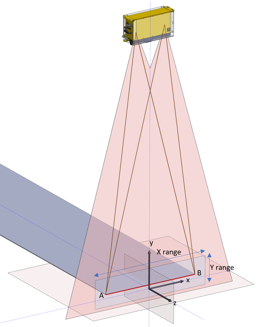
Standard coordinate |
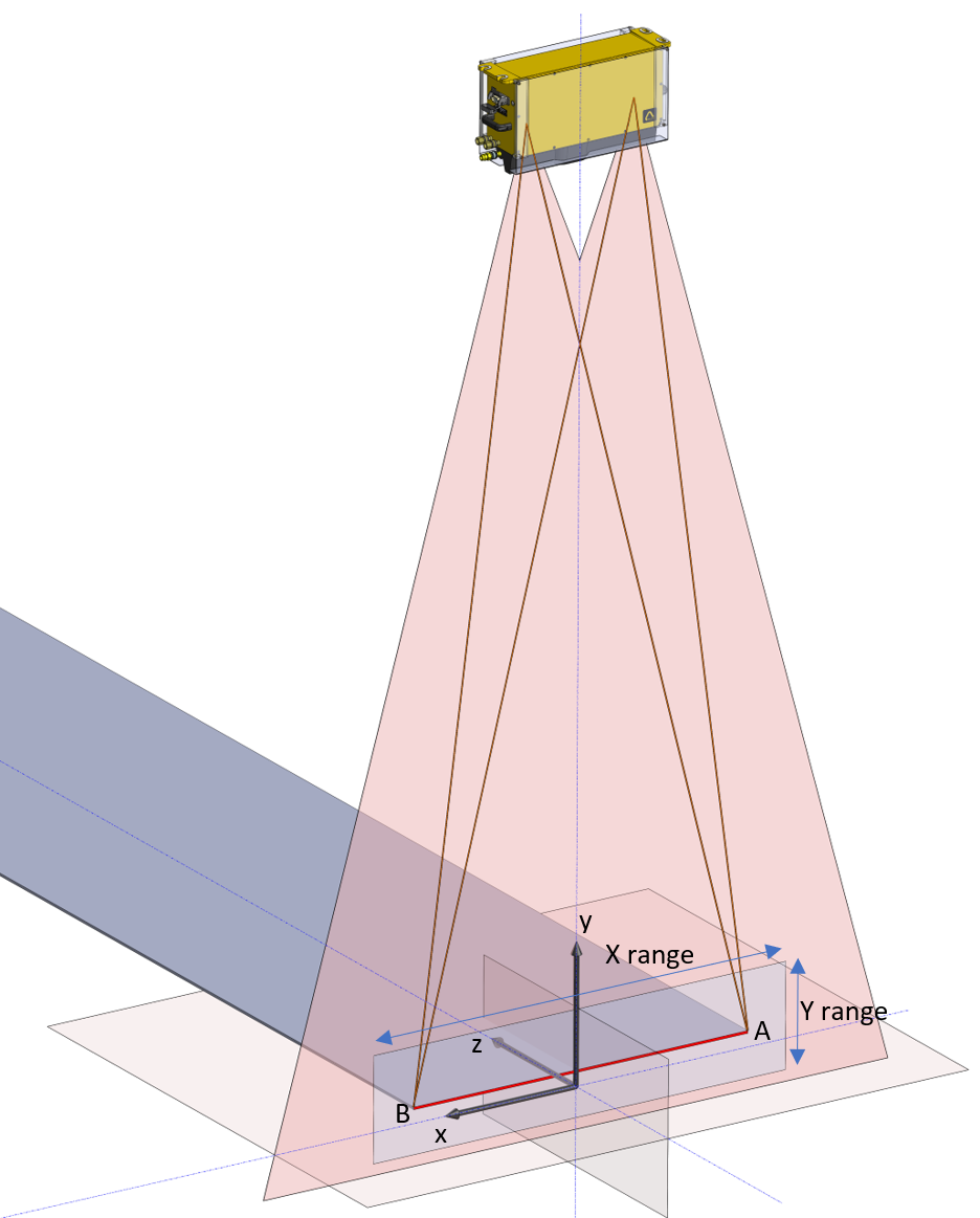
X axis inverted |
The Measurement Window establishes the valid measuring range of the gauge. The Gauge is calibrated at the factory for the specific dimensions of each installation. The Gauge coordinate system has its origin (0,0) a fixed distance from the back of the Gauge Camera Enclosure. This origin is determined during calibration of the gauge. The measurement window is a two dimensional area which defines valid measurements. Edges detected outside this window will be considered invalid and will not generate width measurements. Normally the total x-axis range is set just beyond the maximum possible product width for the particular application. The total y-axis range can be as much as about 20 inches (500 mm), but may be decreased if extreme environmental conditions (such as steam) interfere with proper Gauge operation. The measurement window is established by the following coordinates. Coordinate parameters are set in the Gauge setup menu. Window parameters are defined in the Diag screen.
Note: Invert X axis impacts graph display and gauge outputs. The cameras in diagnostic menu are not inverted.
- Alignement process:
Mount the gauge on its support,
Adjust the gauge horizontally,
In standard coordinate, the slot 1 will be placed on gauge connector side, if “Invert X axis” is checked in gauge setup menu, the verification fixture will be placed on the opposite side.
Place the Verification Fixture on the Roll Table in line with the gauge. Make sure that there is no dust on the glass. Note the verification fixture is supplied with a support for placement on the roll table,
Align and center the verification fixture with the rolls,
With a PC, start the web browser : URL XD4100-xxx/ or IP address (in case of connection through WIFI connect to the SSID : XD4100-xxx, gauge IP address: 172.24.1.1),
Click “Diag” menu and click “Login”: Login: delta, Password: xd,
Switch on the laser, click “Laser ON”
Rotate the gauge to have the laser line parallel to the Verification Fixture,
Shift the Verification Fixture to be aligned with the laser,
Power on the Verification fixture
Check the Width Reading; The Width Reading should be close to the Verification Length.
Check the centreline position and shift the gauge in order to get around 0
Switch off the laser.
Note: the laser should be turned off during measurement – verification, standardization or operation.
Verification of the gauge accuracy#
- Verification process:
Place the Verification Fixture horizontally on the Roll Table in line with the Gauge. Make sure that there is no dust on the lights.
In standard coordinate, the slot 1 will be placed on gauge connector side, if “Invert X axis” is checked in gauge setup menu, the verification fixture will be placed on the opposite side.
Switch on the laser
Align the Verification fixture with the laser
Switch off the laser.
Start the verification, click: Verification,
If the verification is not within the gauge accuracy, start a standardization, click Standardization,
Make a new verification to confirm the gauge accuracy, click Verification,
Remove the verification fixture.
The verification report is available in the “Log” window, Verification.
The gauge is ready
Dimensions#