
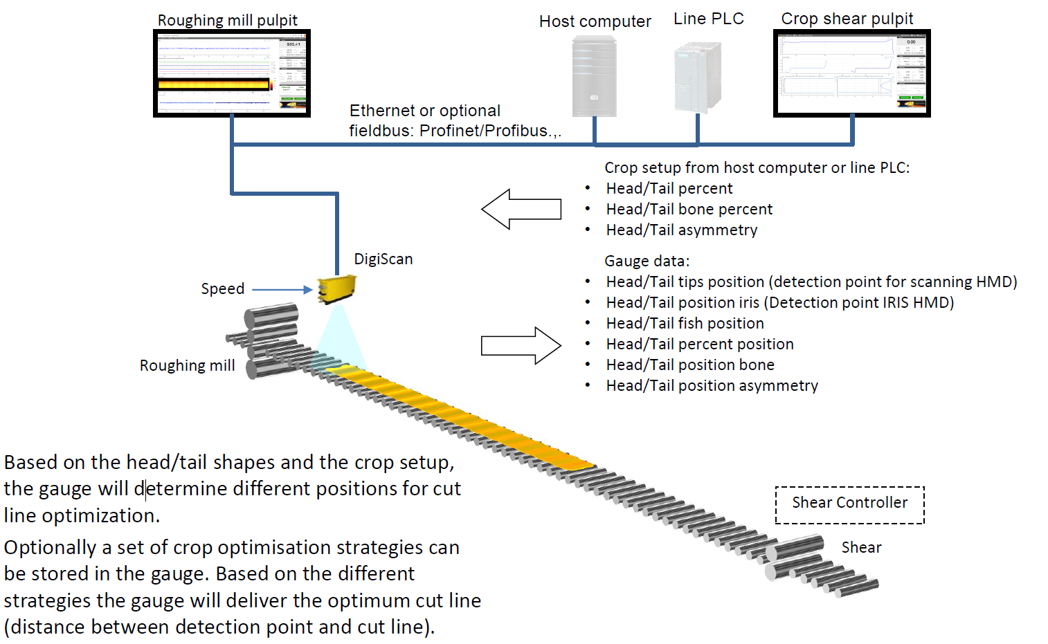
Option Crop View#
This option displays head and tail of the strip: refer to the screen below. For gauge positioned after rougher, this option displays head and tail shape of the bar for crop optimization. It computes the cutline positions according to several configurable criterions (Fishtail line, Percent line, Dog bone and Asymmetry) and supply to the CropShear PLC the distance between those lines and the detection point (ex: HMD like IRIS or DC4500).
It’s necessary to provide an accurate speed to the gauge.
Optionally cut strategy can be managed by the gauge thanks to its plugin feature. The appropriate strategy for each bar is sent by host computer in the setup message, and will be applied by the gauge to determine the cut line position.
Cut line criteria#
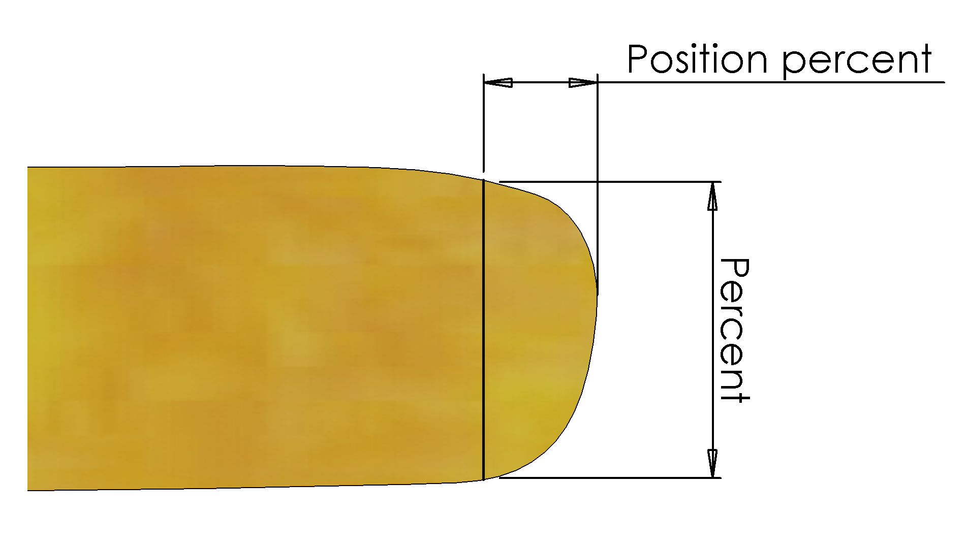
Percent Cut Criterion
The percent Cut criterion states a width minimum percentage tolerance that the end of the bar must fulfil after it has been cut. For example, if the base width is calculated to be 1000 mm, and the Percent Cut criterion is 90%, the cut line will be located at the point where the bar is 900 mm wide.
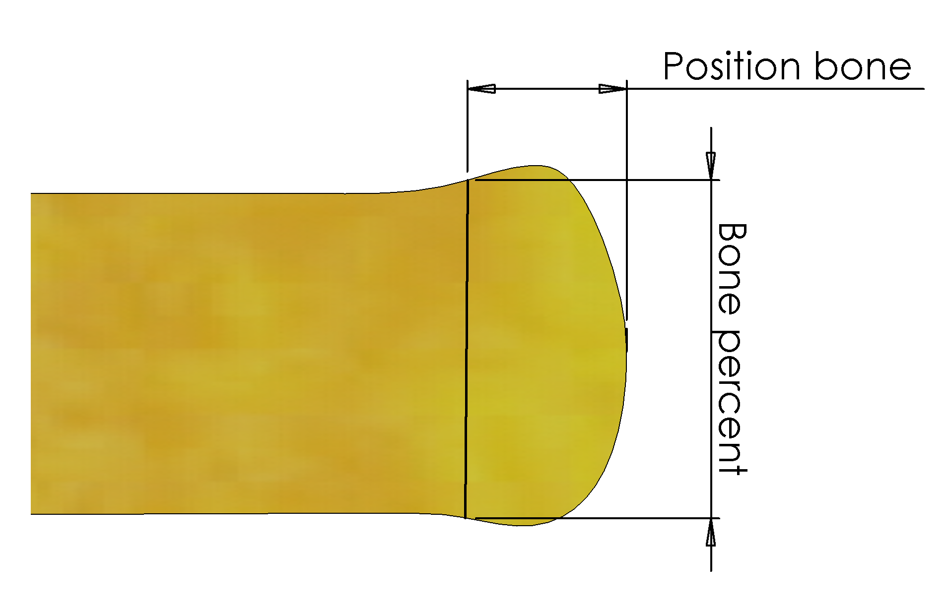
Dog Bone Criterion
If a bar end is determined to have “Dog Bone” shape, the criterion states a width maximum percentage tolerance. For example, if the base width is calculated to be 1000 mm, and the Percent_Bone Cut criterion is 105%, the cut line will be located at the point where the bar is 1050 mm wide.
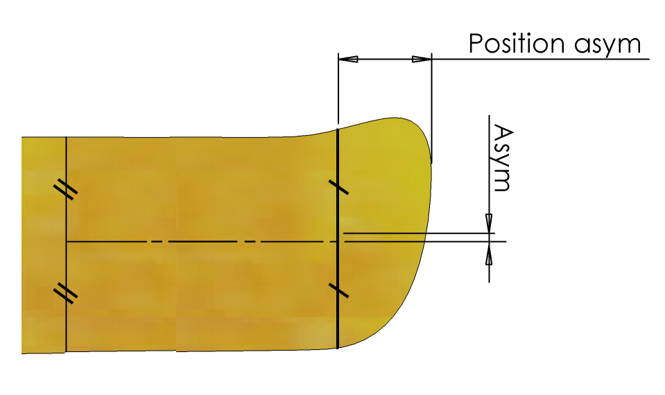
Asymmetry Criterion
If a bar end is determined to be asymmetric, the criterion states a maximum asymmetric tolerance. For example, if the asymmetry cut criterion is set to 50 mm, the cut line will be placed to have a maximum difference between the base centreline and the head/tail centreline of 50 mm.
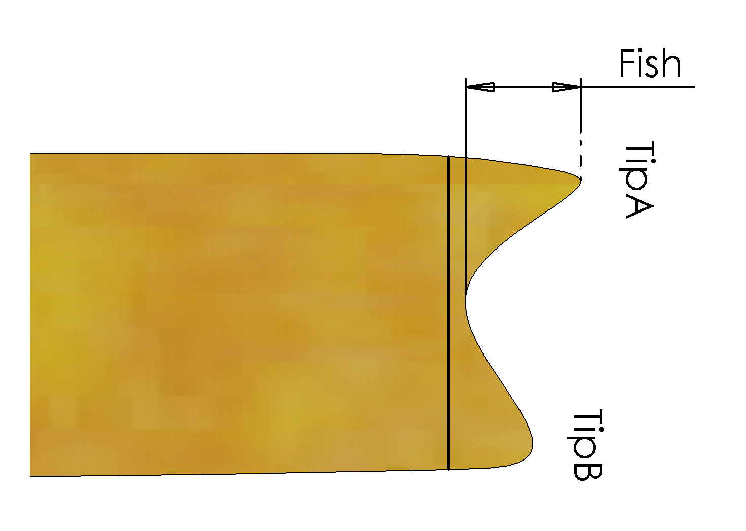
Fishtail Criterion
If a bar is determined to have a “fishtail” shape, the fishtail criterion specifies how much solid material must connect the two “ears” of the fishtail crop.
Crop view architecture#
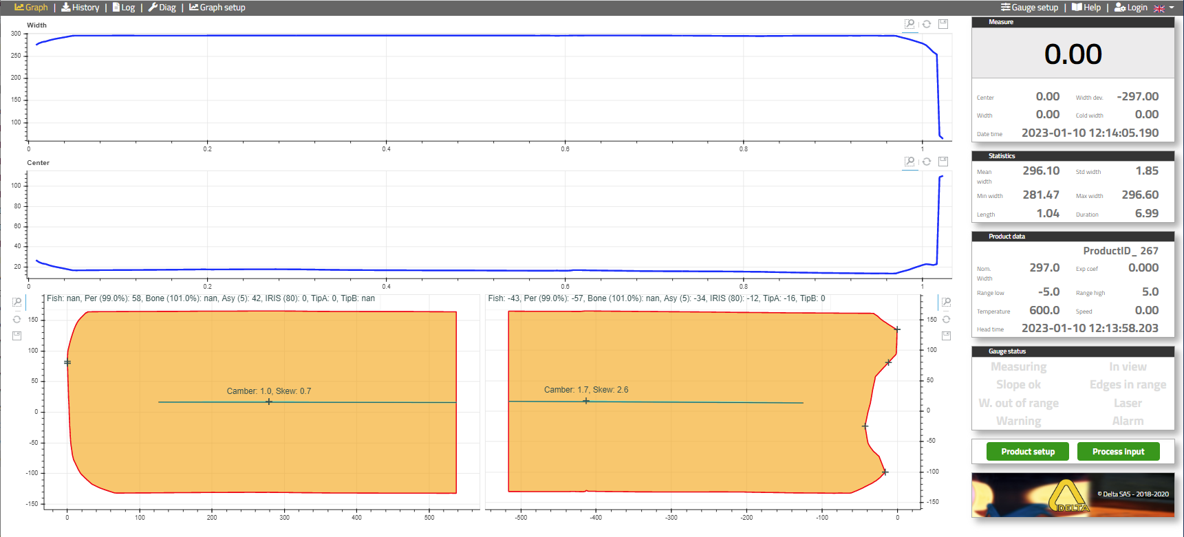
Crop view display#
Crop view gauge setup#
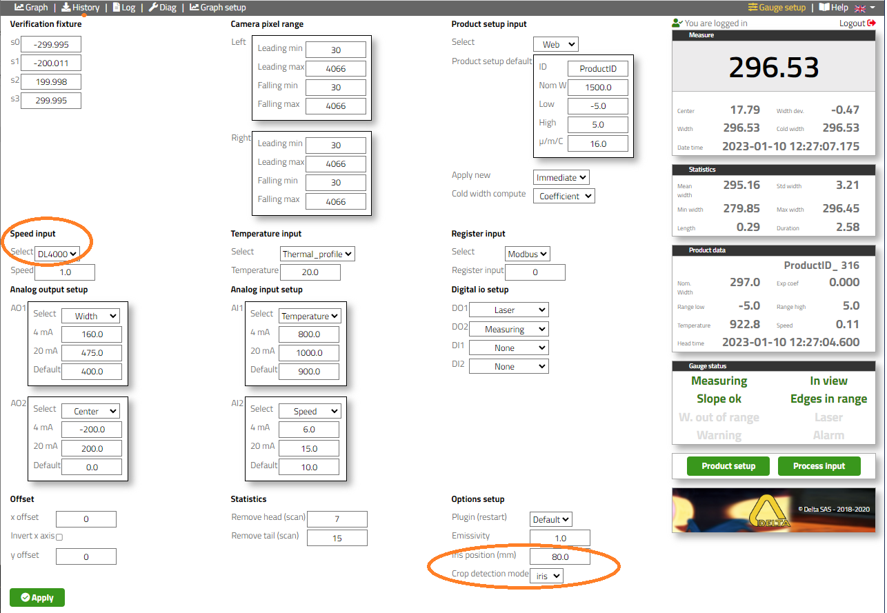
- Menu “Gauge setup”
Speed data is required for this option, and the performance of this feature is depending on the speed accuracy.
The head / tail “Crop detection mode” is defined by the technologie of the sensor: detection of the tip “DC”, use of scanning HMD such as Rota-Sonde DC4500 or point detection “IRIS”, use of fiber optic HMD for installation below pass line.
In case of the use of IRIS, its position “IRIS position (mm)”
Crop view history#
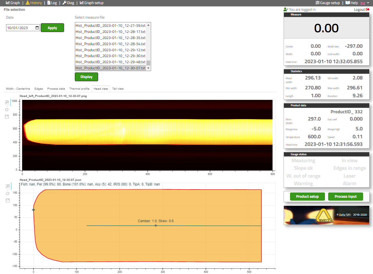
- Menu “History”
Select “Date”
Select “Measure file”