
Option EtherNet/IP#
Physical connection#
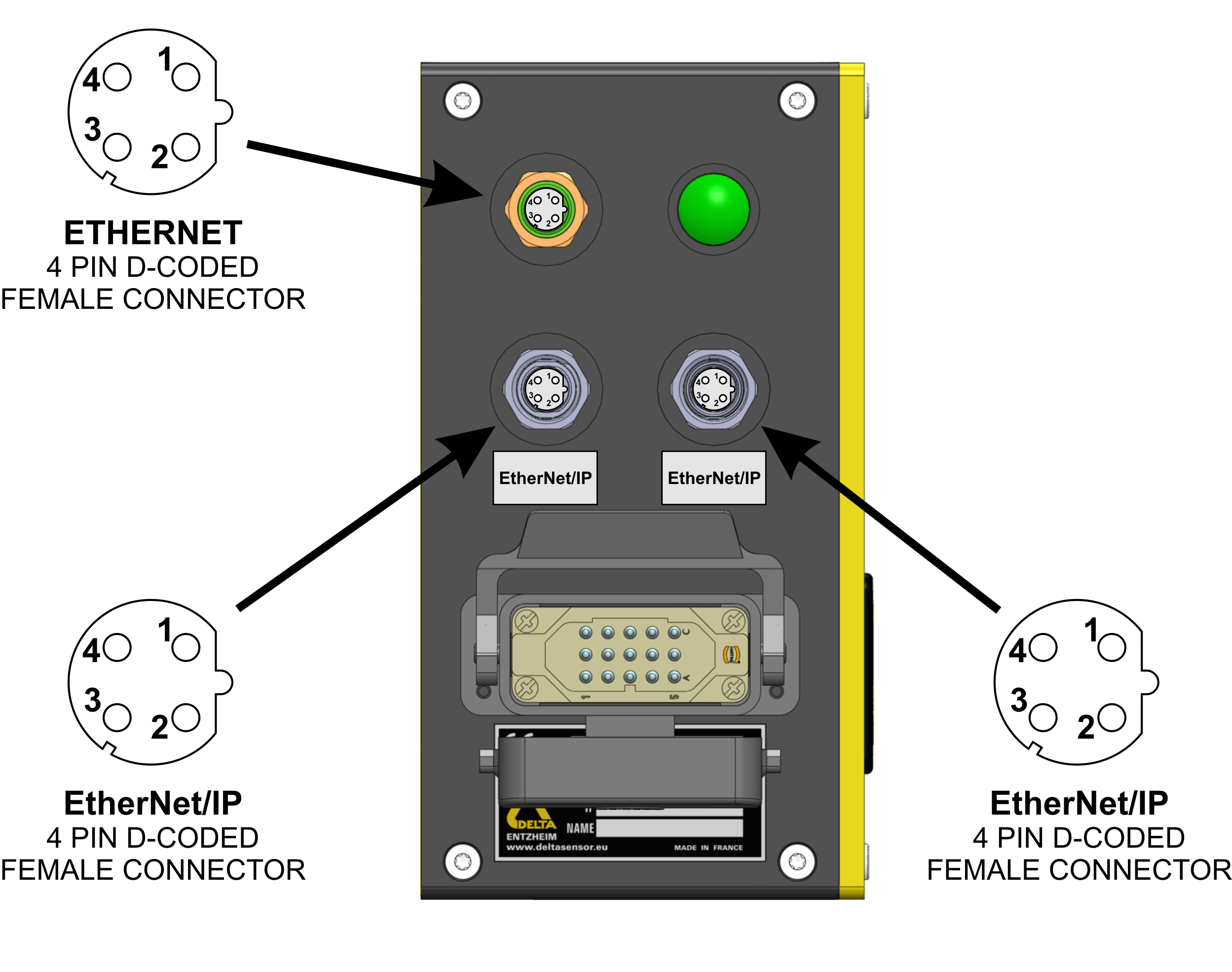
The physical connection to the EtherNet/IP fieldbus is achieved using two shielded twisted pairs (four wires) for data transmission
Connectors#
The gauge supplies two additional M12 Profinet D-coded connectors to link with the EtherNet/IP fieldbus
Note
The EtherNet/IP M12 connectors should be covered when not used
Configuration#
EtherNet/IP address#
Note
An EtherNet/IP system requires at least one scanner and one adapter. Each XD4100 EtherNet/IP communication module is identified by its own IP address. The IP address is assigned using the BOOTP/DHCP EtherNet/IP Tool (which can be downloaded online), based on the device’s MAC address. The MAC address is written on the device’s identification label. Once assigned, this IP address is entered in the PLC configuration to communicate with the device.
The XD4100 communication module can be configured with a static IP address either prior to delivery or via BOOTP. If configured prior to delivery, the IP address will be written on the device’s label. To assign a static IP, first ensure the device is connected to the network. Launch the Rockwell BOOTP/DHCP tool and select the appropriate network interface. Power ON the XD4100 and verify the MAC address on the device label; the MAC ID should appear in the Discovery History window. Select the device and click Add to Relation List. In the New Entry dialog, the MAC address is automatically filled. Enter the desired static IP address, and optionally, the Hostname and Description. Click OK to confirm. Once the device appears in the Relation List, select it and click Disable BOOTP/DHCP. Verify in the Errors and Warnings tab that the command was successfully applied. Finally, power OFF the device for at least 2 seconds and power it back ON to apply the configuration. The XD4100 now operates with the assigned static IP.
EDS file#
An EDS configuration file is supplied with the product on the gauge’s network drive at the path : /documentation. This file conforms to the ODVA Electronic Data Sheet (EDS) specification for CIP networks (EtherNet/IP), ensuring compatibility with standard configuration tools.
Hint
It can also be downloaded on the deltasensor website
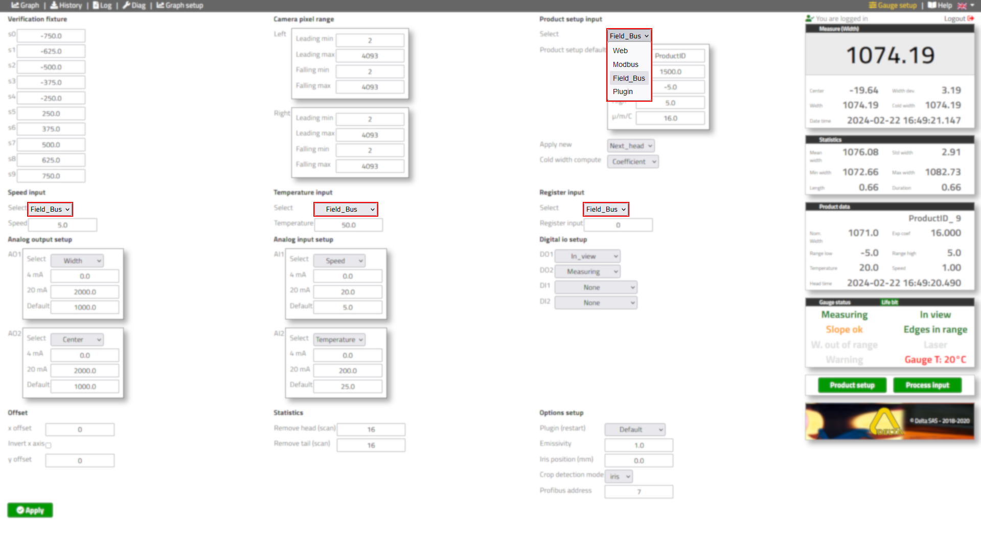
Source selection#
Important
Select the fieldbus to be the source of the product setup, speed, temperature and digital inputs in the gauge setup
Data exchange#
Data will be transmitted in little endian (I)
Input data#
Note
Measurement data : gauge (adapter) -> PLC (scanner)
Indices#
Info
All entries are DINT : signed double integers which use 4 bytes (32 bits)
Index |
Name |
Format |
Unit |
Option |
I0 |
Status |
(see below) |
bitfield |
Standard |
I1 |
Duration |
DINT |
ms |
Standard |
I2 |
Length |
DINT |
0.001 m | 0.001 ft |
Standard |
I3 |
Width |
DINT |
0.01 mm | 0.001 in |
Standard |
I4 |
Cold width |
DINT |
0.01 mm | 0.001 in |
Standard |
I5 |
Width dev |
DINT |
0.01 mm | 0.001 in |
Standard |
I6 |
Center |
DINT |
0.01 mm | 0.001 in |
Standard |
I7 |
Ax |
DINT |
0.01 mm | 0.001 in |
Standard |
I8 |
Ay |
DINT |
0.01 mm | 0.001 in |
Standard |
I9 |
Bx |
DINT |
0.01 mm | 0.001 in |
Standard |
I10 |
By |
DINT |
0.01 mm | 0.001 in |
Standard |
I11 |
Speed |
DINT |
0.01 m/s | 0.01 ft/s |
Standard |
I12 |
Temperature |
DINT |
0.01 °C | 0.01 °F |
Standard |
I13 |
Gauge temperature |
DINT |
0.01 °C | 0.01 °F |
Standard |
I14 |
Reserved |
|||
I15 |
Head tipA |
DINT |
mm | 0.01 in |
CropView |
I16 |
Head tipB |
DINT |
mm | 0.01 in |
CropView |
I17 |
Head fish |
DINT |
mm | 0.01 in |
CropView |
I18 |
Head position percent |
DINT |
mm | 0.01 in |
CropView |
I19 |
Head position bone |
DINT |
mm | 0.01 in |
CropView |
I20 |
Head position asym |
DINT |
mm | 0.01 in |
CropView |
I21 |
Head position iris |
DINT |
mm | 0.01 in |
CropView |
I22 |
Head initial cut |
DINT |
mm | 0.01 in |
Slider |
I23 |
Head cut |
DINT |
mm | 0.01 in |
Strategy |
I24 |
Head weight |
DINT |
kg | lb |
Strategy |
I25 |
Head area |
DINT |
cm² | in² |
Strategy |
I26 |
Head skew |
DINT |
mm | 0.01 in |
SV6000 |
I27 |
Head camber |
DINT |
mm | 0.01 in |
SV6000 |
I28 |
Head length |
DINT |
mm | 0.01 in |
SV6000 |
I29 |
Tail tipA |
DINT |
mm | 0.01 in |
CropView |
I30 |
Tail tipB |
DINT |
mm | 0.01 in |
CropView |
I31 |
Tail fish |
DINT |
mm | 0.01 in |
CropView |
I32 |
Tail position percent |
DINT |
mm | 0.01 in |
CropView |
I33 |
Tail position bone |
DINT |
mm | 0.01 in |
CropView |
I34 |
Tail position asym |
DINT |
mm | 0.01 in |
CropView |
I35 |
Tail position iris |
DINT |
mm | 0.01 in |
CropView |
I36 |
Tail initial cut |
DINT |
mm | 0.01 in |
Slider |
I37 |
Tail cut |
DINT |
mm | 0.01 in |
Strategy |
I38 |
Tail weight |
DINT |
kg | lb |
Strategy |
I39 |
Tail area |
DINT |
cm² | in² |
Strategy |
I40 |
Tail skew |
DINT |
mm | 0.01 in |
SV6000 |
I41 |
Tail camber |
DINT |
mm | 0.01 in |
SV6000 |
I42 |
Tail length |
DINT |
mm | 0.01 in |
SV6000 |
I43 |
Head height |
DINT |
mm | 0.01 in |
CropView |
I44 |
Tail height |
DINT |
mm | 0.01 in |
CropView |
I45 |
Temperature center |
DINT |
0.01 °C | 0.01 °F |
Thermal |
I46 |
Temperature A1 |
DINT |
0.01 °C | 0.01 °F |
Thermal |
I47 |
Temperature B1 |
DINT |
0.01 °C | 0.01 °F |
Thermal |
I48 |
Temperature A2 |
DINT |
0.01 °C | 0.01 °F |
Thermal |
I49 |
Temperature B2 |
DINT |
0.01 °C | 0.01 °F |
Thermal |
I50 |
Temperature A3 |
DINT |
0.01 °C | 0.01 °F |
Thermal |
I51 |
Temperature B3 |
DINT |
0.01 °C | 0.01 °F |
Thermal |
I52-54 |
Reserved |
|||
Register I0 : Status#
Info
Detailing the bitfield of I0 with each field of type bit and value boolean
Register
Name
Description
Option
I0.0
Alarm
Internal temperature above 65°C | 150°F
Standard
I0.1
Warning
Warning on water, air, plugin, IO, fieldbus, ext. IO, laser, low disk
Standard
I0.2
Measuring
Measuring system activity
Standard
I0.3
In view
Light level difference satisfying for inview threshold
Standard
I0.4
Head available
Head data is available
Slider
I0.5
Tail available
Tail data is available
Slider
I0.6
Control
Low margin for inview threshold
Standard
I0.7
Width out of range
Measured width is out of the range setup by user
Standard
I0.8
Head initial
Head data is available but not final yet (if slider)
CropView
I0.9
Tail initial
Tail data is available but not final yet (if slider)
CropView
I0.10
In range
Edges position outside the specified range
Standard
I0.11
Reserved
I0.12
Low disk space
Log disk is almost full the gauge will keep working without logging
Standard
I0.13
Life bit
1 second on, 1 second off, the gauge is ready
Standard
I0.14
Reserved
I0.15
Setup pending
New product setup acknowledged, will be applied on next head
Standard
I0.16-23
Reserved
I0.24
Measure disabled
Measuring system is disabled
Standard
I0.25
Laser on
Laser is turned on
Standard
I0.26-31
Reserved
Output data#
Note
Setup data data : PLC (scanner) -> gauge (adapter)
Indices#
Info
All entries are DINT : signed double integers which use 4 bytes (32 bits)
Index |
Name |
Format |
Unit |
Option |
O0-7 |
Product ID |
32 bytes |
ASCII |
Standard |
O8 |
Reserved |
|||
O9 |
Nominal width |
DINT |
0.01 mm | 0.001 in |
Standard |
O10 |
Range low |
DINT |
0.01 mm | 0.001 in |
Standard |
O11 |
Range high |
DINT |
0.01 mm | 0.001 in |
Standard |
O12 |
Exp coef |
DINT |
0.001 µm/°C/m | 0.001 µft/°F/ft |
Standard |
O13 |
Grade |
DINT |
table ID |
Standard |
O14 |
Input register |
(see below) |
bitfield |
Standard |
O15 |
Reserved |
|||
O16 |
Speed |
DINT |
0.01 m/s | 0.01 ft/s |
Standard |
O17 |
Temperature |
DINT |
0.01 °C | 0.01 °F |
Standard |
O18-21 |
Reserved |
|||
O22 |
Nominal thickness |
DINT |
0.01 mm | 0.001 in |
Strategy |
O23 |
Density |
DINT |
kg/m³ | lb/ft³ |
Strategy |
O24 |
Head percent |
DINT |
0.001 |
CropView |
O25 |
Head bone percent |
DINT |
0.001 |
CropView |
O26 |
Head bone percent cut |
DINT |
0.001 |
CropView |
O27 |
Head asym |
DINT |
mm | 0.01in |
CropView |
O28 |
Head fish margin |
DINT |
mm | 0.01in |
Strategy |
O29 |
Head min |
DINT |
mm | 0.01in |
Strategy |
O30 |
Head max |
DINT |
mm | 0.01in |
Strategy |
O31 |
Tail percent |
DINT |
0.001 |
CropView |
O32 |
Tail bone percent |
DINT |
0.001 |
CropView |
O33 |
Tail bone percent cut |
DINT |
0.001 |
CropView |
O34 |
Tail asym |
DINT |
mm | 0.01in |
CropView |
O35 |
Tail fish margin |
DINT |
mm | 0.01in |
Strategy |
O36 |
Tail min |
DINT |
mm | 0.01in |
Strategy |
O37 |
Tail max |
DINT |
mm | 0.01in |
Strategy |
O38-39 |
Reserved |
|||
Register O14 : Input register#
Info
Detailing the bitfield of O14 with each field of type bit and value boolean
Index
Name
Description
Option
O14.0-2
Reserved
O14.3
Disable measure
Disable the measuring system
Standard
O14.4-6
Reserved
O14.7
Freeze head slider
Freeze head cut adjustments
Slider
O14.8
Freeze tail slider
Freeze tail cut adjustments
Slider
O14.9-15
Reserved